|
One
of the most fundamental quantities in the kinetic theory of gases
is the collision cross section
σ. Accurate knowledge of
this quantity is essential in chemical kinetics for the evaluation
of the collision frequency, for example. The quantity σ has
the dimension of an area and is related to the size of the collision
partners. For a selected spherical particle X colliding with buffer
gas particles, the collision cross section corresponds
|

|
to the area of the base of a cylinder aligned along the velocity
vector of X. Since the cylinder base is essentially the projection
of X onto a plane, σ could also be called a projection
cross section of X. In simple hard-sphere terms,
buffer gas particles inside the cylinder will intersect with
the present trajectory of X, particles outside the cylinder
will not collide with X.
For
a macroscopic spherical particle, σ and the collision
radius a
are essentially given by the particle radius and can readily
be measured using microscopy, for example. The size of the
buffer gas can be neglected.
σ = πa2
(1)
For
small particles, however, it is much harder to measure σ.
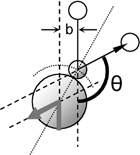
The quantity which ultimately determines whether a collision
between two particles took place or not is the scattering
angle θ, the change in direction of the trajectories
of the two particles involved.
|
|
For
ideal hard spheres, the situation is simple and two particles
either hit or miss. But small real particles on the scale
of atoms and small molecules cannot be considered hard spheres.
Instead, there is a long-range (Lennard-Jones-like) interaction
between the two particles without any sharp cutoff at any
distance.
Hence, the definition of the size of the collision cylinder
becomes less clear. Does a deflection of 10° or 1°
or 0.1° constitute a collision? Where is the cutoff?
|

|
|
Therefore,
the lack of a clear cutoff between collision and miss results
in a poorly defined quantity σ for real (non-hard sphere)
particles. However, the related momentum
transfer cross section Ω
is readily defined for any type and size of particle and
is more readily accessible by experiment even for very small
particles. The experiment involves evaluation of the resisting
force of a particle drifting in a buffer gas under the
influence
of an accelerating field (gravity, electric field). The magnitude
of the momentum transfer in a single collision, given by (1
- cosθ), covers values from 0 (no scattering) up to a
maximum of 2 (head-on collision
with momentum p of particle X turning into -p
in the center of mass
|
|
 |
frame).
Hence, whereas the calculation of σ involves integration
over the projection area elements dxdy
σ
= ∫∫ dxdy , (2)
in
the calculation of Ω, each cross section element dxdy
is scaled by the momentum transfer occurring at the corresponding
position (x,y)
Ω
= ∫∫ (1-cosθ) dxdy
(3)
with
θ = θ(x,y) being a function of x and
y. Therefore, a near head-on collision resulting in
a near maximum change of momentum contributes more to Ω
than a glancing collision with a small deflection angle.
|
|
However,
since the number of glancing collisions is generally much
larger than that of near head-on collisions, glancing collisions
contribute significantly overall. Note, that whereas the integration
in equation (3) is through the entire space (from -∞
to +∞), the integration in equation (2) requires
clear boundaries for σ to take on a finite value. Hence,
for an object without clear boundaries, σ can neither
be unambiguously measured nor calculated without assumptions
about the object's boundaries.
For
a hard sphere with clear boundaries and with a collision radius
a,
the scattering angle as a function of impact parameter b
is given by
θ(b) = 2 cos-1(b/a)
and equation (3) turns into
Ω
= ∫ (1-cosθ) 2πb
db = πa2
= σ . (4)
Hence,
for a hard sphere the momentum transfer cross section is identical
to the projection cross section. Ω of a real particle
X corresponds to the cross section a hard sphere would have
such that the resisting force of the hard sphere drifting
in a buffer gas matches that of X.
|
|
 |
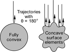
For
a fully convex object with a smooth surface very few collisions
lead to near maximum momentum transfer (with θ near 180°).
For an object with dents in the surface, on the other hand,
there are more possibilities for obtaining large scattering
angles and the momentum transfer cross section is increased
over that of a fully convex object with the same projection
cross section.
|
|
For
a very rough surface the value of θ(x,y) may change very
rapidly for very small changes in x and y. If the dimensions
of the surface roughness are much smaller than the particle
dimension it may appear as if the buffer gas is scattered
randomly in every direction at any given position (x,y). In
this description of the scattering process, there is a distribution
of reflection angles for every position (x,y). This leads
to the phenomenon known as diffuse reflection.
The
resisting force acting on a particle moving through a buffer
gas has been studied experimentally and theoretically more
than a century ago by Langevin, Knudsen, Millikan, and others.
For a sphere of collision radius a
and drift velocity v, theory indicates a resisting
force due to specular scattering given by
F
= 4/3
πa2
d v <c>
(5)
where
d is the buffer gas density and <c>
the average buffer gas particle speed. As discussed above,
assuming diffuse scattering for the same size sphere results
in an increased resisting force of
F
= (4/3
+ π/6)
πa2
d v <c>
(6)
A
range of careful experiments involving small solid and liquid
spheres
(~1 µm diameter) made of a variety of materials, such
as glass balls and oil droplets, show diffuse reflection is
dominant for these systems in air and other gases. However,
very generally all these experiments indicate the presence
of a small fraction (approximately 10%) of specular reflections.
The
ion mobility spectrometry (IMS) method offers a convenient
way to explore the resisting force of any charged particle,
including a particle as small as an atomic ion, drifting in
a buffer gas under the influence of a weak electric field.
Under typical IMS conditions, ions travel with a constant
velocity v which is given by the electric field strength
E
v
= K E . (7)
The
proportionality constant K is the ion
mobility by definition.
The velocity v is constant because the forward accelerating
force of an ion with charge q
F
= q E (8)
is
offset by the resisting force due to collisions of the ion
with the buffer gas
 (9)
(9)
Equations
(7) to (9) lead to the well known equation
 (10)
(10)
which_is
used in the ion mobility community to connect the ion mobility
K with the average momentum transfer cross section
ΩIMS. In these equations N is the buffer
gas number density; µ = m×mion/(m+mion)
the reduced_mass of
the collision partners with masses m (buffer gas) and
mion (ion); k the Boltzmann constant;
and T the buffer gas temperature. Using the relationships
d = mN and <c>
= √(8kT/πm)
and assuming
mion>> m, the equivalence of equations
(5) and (9) is apparent:
ΩIMS= σ = πa2
. For a spherical particle X and specular scattering, the_momentum
transfer cross section is identical with the collision cross
section. However, comparison of equation (9) with equation
(6) (diffuse reflections)_yields
the relationship
ΩIMS
= 1.39 × σ (diffuse reflection)
(11)
with
σ = πa2.
Equation (11) clearly displays how the details of the collision
process can lead to a substantial discrepancy between the
two quantities σ and Ω, the collision
cross section and the momentum transfer cross section, respectively.
It
should be noted, that the mobility-derived experimental measure
of the momentum transfer cross section, ΩIMS
(equation 10), is an average value with respect to collision
energy and ion orientation. Except for hard spheres, θ
(and therefore Ω; see equation 3) is a function of collision
energy and consequently the IMS experiment delivers an energy
distribution-weighted average of Ω values. Furthermore,
for non-spherical ions, the experimental value is also an
average over all possible orientations in space. Hence, for
real molecular systems, equation (3) applies only for one
particular collision energy and one particular ion orientation.
Therefore attempting a theoretical calculation of the momentum
transfer collision cross section (or collision integral as
it is sometimes called), ΩCALC,
involves evaluation of equation (3) as a function of energy
and orientation and the resulting Ω values have to be
properly averaged.
|
|
|
Since the resisting force probed in an IMS experiment depends
on the distribution of scattering angles θ in individual
collisions, ΩIMS
of a polyatomic ion is affected by the shape of the molecular
framework. Hence, the makeup of the molecular surface giving
rise to the dark gray projection area σ in the figure
matters. It makes a difference whether the cross-hatched surface
(see top of sphere in the figure) is smooth or rough, flat,
convex, concave, or rippled. The scattering of particles hitting
the surface from the top is obviously different for different
surface makeups and average momentum transfer is increased
for a rough surface compared to a smooth convex surface (see
also previous figure above).
|

|
|
Therefore it is important for any theoretical model attempting
to quantify the resisting force of a drifting polyatomic ion
with a given projection cross section to incorporate an accurate
and appropriate description of the concaveness of the ion
surface.
The
projected superposition approximation
(PSA) is an algorithm we recently developed to
quantify the resisting force of a drifting ion with a given
molecular geometry. In this model an estimate of the shape
effects or surface effects is an integral part with the result
given in form of a shape factor ρ which is used to scale
an orientation-averaged projection cross section σPSA
according to surface concavity or surface roughness
ΩPSA = ρ × σPSA
. (12)
In
the PSA algorithm, the computation of σPSA
takes buffer gas interaction effects including superposition
effects into account.
The
shape factor ρ is a measure for the concaveness of the
molecule relative to a purely convex molecule of the same
size. Whereas a lot of details have to be taken care of in
the computation of ρ, the basic concept applied in PSA
is simple: ρ is essentially the ratio of the actual molecular
surface area Amol
of a molecule to the surface area Aref
of a reference structure
ρ
= Amol / Aref .
(13)
The
reference structure has essentially the same shape as the
molecule itself but it does not have any dents or cavities;
the reference surface is essentially fully convex. As an approximation
of this reference structure we are searching for a structure
in PSA which fully encloses the molecular structure and which
has a minimum surface area Aref.
For
instance, a cube with dents in the surface (left cube in the
figure below) has a larger resisting force when drifting in
a buffer gas than a cube without dents (right cube) even though
the respective orientation-
|
|
|
averaged
projection cross sections of the two cubes are exactly identical
(and therefore σleft
= σright).
But the left cube transfers more momentum per collision on
average than the right cube and therefore
Ωleft
> Ωright.
Since
for the left cube
|

|
|
Amol
> Aref,
the PSA shape factor is larger than 1 and equation (12) increases
Ω accordingly over σ. For the right cube, on the
other hand, Amol
= Aref,
and Ω = σ.
|
|
|


